Adding a Backstay Adjuster
Submitted by Jon Vez
Following is the procedure I used to install a backstay adjuster on my 1999 320. This method requires no drilling and will work fine if you use a bimini.
The 320 has a substantial masthead type mast with no real ability to bend, so the purpose of the adjuster is not to induce mast bend, but to tighten the forestay when sailing upwind. Tightening the forestay allows you to point higher, reduce heel, and lessens the tendency to round up in strong breezes.
This configuration also allows you to back off the tension on your backstay for improved sail trim when off the wind. Many sailors see a backstay adjuster as an upgrade just for racers, but I believe that this upgrade is equally compelling for cruisers as well. Having a well trimmed boat with less healing and better upwind performance simply adds to the pleasure of sailing!
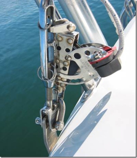
To create the attachment points for the adjuster, you will simply replace the clevis pins at each backstay tang with a D shackle. The pin that comes with the D shackle replaces the original clevis and the ‘D’ portion becomes your attachment points for the adjuster’s blocks and tackle.
I chose to create an adjustment on each side of the backstay. I originally took this approach to increase purchase, but there is the added benefit of creating less clutter in the cockpit. The starboard side is my ‘course’ adjustment and the leeward the ‘fine’ adjustment.
The actual installation time was about 3 hours for two people including tuning the rig.
Here is the parts list:
2 - D Shackles with 3/8” Clevis Pins (Photo #1)
1 - Harken Triple Bullet Block (part #086)
1 - Harken Triple Bullet with Cam & Becket (part #095)
3 - Harken 308 2.0 Single wire blocks
1 - 6mm, 2mm ID Stainless Ring (Part #94-21)
1 - Single ratchet block w/cam (if you choose to use a single adjustment setup, you do not need this block)
20 - Feet of low stretch line (I used T900) with splice to part #086
30 - Feet of 5/16” Sta-Set spliced to part #095
The steps involved:
- Ease the backstay tension by loosening the toggles as much as possible. Create a bridle by running a line attached to each stern cleat (you will use this to attach the main halyard to in order to support the mast while you are changing out the clevis pins, so make sure the line is strong enough for this job!)
- Attach your main halyard to the bridle and winch the halyard tight. You will need enough tension to create enough slack to completely back off each backstay toggle.
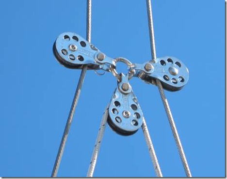
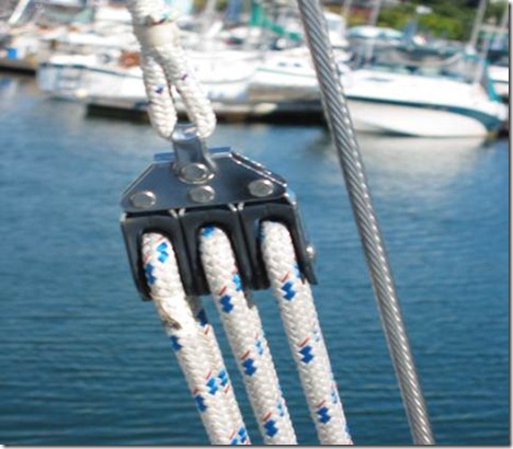
- Assemble the 3 wire sheaves around the Stainless O-Ring to create the adjuster and run each back stay leg through the appropriate sheave (photo #3).
- Remove the old clevis pin and replace with the 3/8 pin & D-shackle and reattach the backstay shrouds. You can now back off and remove the bridle set up.
- Attach the ratchet/cam blocks to each ‘D’ shackle and rig the tensioning lines. (*Note: If you only want to use one side to adjust your backstay, simply terminate one side to the D shackle and attach a ratchet/cam block to the other.)
- Run the 20 feet of line from through the lower wire block and run the bitter end through the starboard side ratchet block. This is your ‘course’ adjuster. The spliced end will be on the port side spliced to the triple bullet block (photo #4)
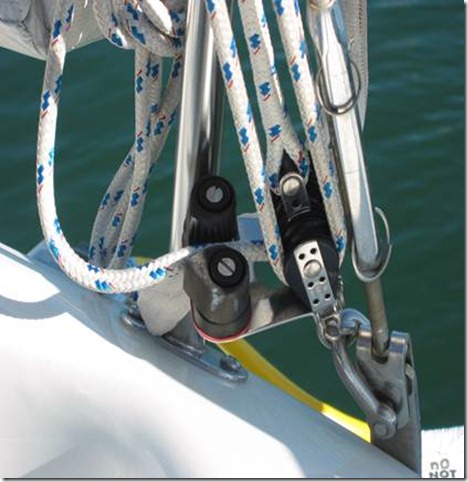
- Rig the 30 feet of line through the triple bullet block and down to the bullet block with cam and becket (photo #2)
- Tune the rig. Using a Loos gauge, back off the backstay tension as much as possible. Take gauge readings while tensioning the backstay with the new adjuster to find the ‘neutral’ tension—the tension you had before the adjuster was installed. Mark this location on the coarse side with a permanent marker. Tension up your backstay as much as you can and mark the line here as well. In this position the forestay should be bar tight and will be the upwind position.
- Go sailing!!
Photo 1: D Shackle with 3/8 clevis-replaces original clevis & Starboard side cam
Photo 2: Port side adjuster
Photo 3: Turning blocks that make up the adjuster
Photo 4: Triple Bullet block (Harken part #086)
